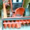
illinilefttackle 399 #1 Posted May 5, 2015 Hello Gents- Just working on the A-81/11 that Brought back to usefulness. I used the electrical s on the A-81 with just a "run" & "Off" position on the ignition switch. Since the Briggs engine I used was an electrical start, I used a Ford 3 terminal Solenoid I had laying around and a momentary push button to start it. MY QUESTION: The motor has a stator and it tests out good- it has two wires coming off it, red & black-tested voltage on the black one and amps om red one. 14 volts- 3 amps. Tractor it was on had Headlights, used the red wire to drive them. Its a 1987 Briggs 12 hp vertical engine. How & where do I dump this current from the stator into the battery to charge it? Thanks in advance for any help- Al Share this post Link to post Share on other sites
Save Old Iron 1,568 #2 Posted May 5, 2015 Al, the stator should be two separate windings. One should be about 14 to power headlights. The second wire may have a "lump" in it covered with heat shrink tubing or electrical tape. This would be the charging wire for the battery. Temporarily connect this lumpy wire to the battery. The battery voltage should jump above 13 volts with the engine running. 1 Share this post Link to post Share on other sites
Save Old Iron 1,568 #3 Posted May 5, 2015 (edited) check out page 16 and 22 of manual - battery charge should come from the RED wire. http://www4.briggsandstratton.com/miscpdfs/RNT/alternator_replacement.pdf Edited May 6, 2015 by Save Old Iron 1 Share this post Link to post Share on other sites
illinilefttackle 399 #4 Posted May 5, 2015 Is Stator grounded already? So you connect Red wire to Positive of Battery- Correct? Thanks- Al Share this post Link to post Share on other sites
Save Old Iron 1,568 #5 Posted May 6, 2015 The low amperage Briggs systems have both windings grounded thru the stator / engine mounting bplts. A quick ohms measurement can detect this and a visual could confirm it. 1 Share this post Link to post Share on other sites
illinilefttackle 399 #6 Posted May 6, 2015 Thank you Mr Squirrel- the depth of your understanding of electrical components amazes me. I got it done- works great! Not sure if I needed it- but I put a toggle switch in the circuit going to the positive post of the battery- since its not going thru a Ignition switch. Your explanation of the "bumpy" wire was classic. I understood that the stator was making AC current - so it needed a diode to chop the Sine wave in half and get pulsating DC to charge the battery- Thanks again- Al Share this post Link to post Share on other sites
Save Old Iron 1,568 #7 Posted May 7, 2015 Excellent. Glad it worked out. Keep an eye on both the battery voltage and electrolyte level if the battery has fill caps. 1 Share this post Link to post Share on other sites