Search the Community
Showing results for tags 'tutorial'.
Found 14 results
-
I have a GT-14 that was in need of a replacement Hydro Gear and had a good unit from a Ranger that was a direct bolt up except for the output gear being the wrong size. Since I could find nothing in the Manual and no previous tutorial on this subject I dicided to dive into and take a few photos along the way. Step one was to remove the 4 1/4-20 bolts that hold the retainer on the inside of the unit on both Hydros. (see first photo) Step two was to remove the 8 3/8 and 2 5/16 bolts that hold the outer cover and split the outer casting from the rest of the unit. I used a gasket scraper to get it started and then a couple of wood wedges. DO NOT SRATCH THE SURFACES, THEY ARE MACHINED AND THERE IS NO GASKIT! Now you will use snapring pliers to remove the spring clip. (see second and third photos) Step three was to remove the shaft that has the output gear on it. If you have a press that would be a good thing, but not having one i used a large punch and eight oz. hammer and carefully drove the shaft and the captive roller bearings. As you remove the shaft the inner gear of the hydralic motor will come off the shaft, be sure the key for the motor gear comes out with it. Once you have the shafts out of both units you can put the shaft from your old unit into the replacement unit. Press or drive the shaft and captive roller bearings into the new hydro Gear Motor. take a moment to rotate the gear for time to time to be sure nothing is binding. (see fourth photo) The final step is to put on the spring clip and bolt everything togather. I found that a clamp on the shaft helped hold it in place while puting on the spring clip. While you are bloting the cover and retainer togather be sure to rotate the shaft from time to time to be sure nothing is binding. All things considered this is not too complicated, and realy no special tools needed. Hope this will be of help to Red Square members.
-
Hi Just bought my 312 this spring when we moved into a new home with two acres of land. Love the wheel horse, but I am not even sure if I have to change a oil filter and for that matter where the filter or oil plug would be - any guidance would be appreciated. Put a little marvel mystery oil in the gas, and just started it up for a few, but want to change the oil for the spring. Any guidance on where to start would be greatly appreciated.
-
I know when this subject came up a year or so back, I put together a quick drawing on how I used to duplicate a tractor wiring harness using a section of plywood as a guide. I recently broke down and purchased an expensive open terminal crimper to do a half dozen or so C series harnesses for family and friends. I figured "In for a dime , In for a dollar" and decided to share a real life example of a harness replication jig. The board is just a scrap piece of MDF which was either going into the garbage or was going to be put to some temporary but significant use. Some scrap MDF shelving laying next to a C series in need of repair and Bingo -here we are. If the original harness can be pulled out of the tractor without too much damage, layout the harness on the board in a logical arrangement which will make use of all the landscape on the board. Major connection points can be held in place with screws or rotating screen door latches. The same latches can be used to call out major artery junctions in the harness. The latches can be used to secure the old harness to the board and create the jig The latches can be rotated to allow easy removal of the old harness or the completed new harness. Single wires can held in place with wire hold-downs used for bell cable or speaker wire. The length of all the OEM wiring is called out and the jig allows for increasing the length of wiring as required for custom installs. The crimpers and terminal rings should arrive early next week. I'll finish, wrap and test the new harness and post additional pics at that time.
- 18 replies
-
- 6
-

-
- c-series
- electrical
-
(and 2 more)
Tagged with:
-
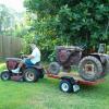
Hey everyone. As you know I'm hot and heavy into wheel horses now and many of you have answered many of my questions and helped me TREMENDOUSLY. But I've finally decided to give my horse a paint job and I thought I'd post pictures along the way. Here's the engine cleaned,sanded, prepped and primed. This is the first thing I've done. :)
- 240 replies
-
- 3
-

-
- vertical-shaft
- engine
-
(and 6 more)
Tagged with:
-
Hello on my kawasaki 227-5 17 hp single cylinder i was thinking about putting a straight through pipe on it and people time and time again were mentioning burnt or warped exhaust valves and i have no idea how bad this is or how common it is so i just want to know if i should or shouldn't straight pipe the engine thank you James see my other thread about tachometer gauges
- 5 replies
-
- d-series
- 200-series
-
(and 4 more)
Tagged with:
-
Hi RedSquare, I am in the process of restoring a wheel horse 857 and i have just received decals to put on the machine but in not to sure how to put them on and protect them from getting scraped off. any suggestions? Thanks
- 5 replies
-
- tutorial
- general discussion
-
(and 1 more)
Tagged with:
-
I'm thinking of mounting farmall cub headlights (the thin looking ones) to my 753. I know they're not original wheel horse obviously and I'm usually a stickler with that type of deal but I think they would look good. Is this a bad idea in you're guys' opinion?
- 3 replies
-
- electrical
- tutorial
-
(and 4 more)
Tagged with:
-
Hey again guys. My 753 tractor has an hour meter installed on it. (Very neatly done.) It says it now has 1739 hours on it. I would say it might have a little more than that if its not original which I'm guessing its not? The meter does appear old though. How long can a trans last in a 753. (Approximately) I know you can't tell me exactly but it doesn't jump out of gear going up or down hill. Just wondering. Thanks guys, I appreciate it, Zane
- 4 replies
-
- transmission
- tutorial
-
(and 2 more)
Tagged with:
-
Please note the position of the "band" on the diode and what color lead (positive / red or negative / black) is connected banded lead of the diode. Diodes are the equivalent of check valves in the world of plumbing or hydraulics. Current should only flow in one direction thru the diode. Current flow should be present when the negative / black lead of the multimeter is connected to the banded lead of the diode and the positive / red lead is connected to the opposite lead. (click on image to enlarge) The diagram below shows a defective diode that has an internal short circuit in the body of the diode. The diode no longer has a "one way" characteristic and acts as if it were a piece of wire - current will flow in either direction thru the shorted diode so meter lead orientation makes shows no difference. In the world of plumbing or hydraulics, the check valve would be "stuck open". The defective diode below is the equivalent of a burned out fuse. No current can flow thru the diode in either direction. The meter readings show a high resistance to current flow in either lead orientation. The hydraulic equivalent would be a check valve was "stuck closed".
- 2 replies
-
- 1
-

-
- c-series
- electrical
-
(and 1 more)
Tagged with:
-
Unevenness or warp in the gasket sealing surface of a cylinder head may cause vacuum or pressure leaks in the combustion chamber. If left unchecked, cylinder head distortion may result in less than optimum engine performance and visible symptoms including oil leaks around the head area and possible blowout of the head gasket material. If hot combustion gases are allowed to continue to leak past the aluminum head, erosion of the aluminum gasket sealing surface can occur and render the cylinder head useless. The procedure below explains how to renew a flat(ter) surface on the cylinder head gasket sealing area to prevent defects in the gasket surface from destroying additional head gaskets or the cylinder head itself. Float glass is certainly not the end all argument for a perfectly flat surface but can easily provide sufficient flatness for the purpose of improving the sealing capability of a LGT tractor cylinder head. In preparation for renewing the cylinder head, a few common items will need to be obtained from local suppliers. The surface of an ordinary pane of glass makes a very suitable flat surface to perform this procedure. Several sheets of Wet/Dry 220 grit waterproof paper will be required. Water in a spray bottle will be needed to wet the abrasive paper to keep aluminum debris from collecting on the abrasive paper and clogging the grit prematurely. Wetting the glass pane slightly will allow the paper to "suction cup" itself to the glass pane when the cylinder head squeegees the water from underneath the paper. The cylinder head pictured below will be used for this process. This is a high compression head from a Cub Cadet 10HP Kohler engine. To observe the progression of material removed from the head, I apply a very light "guide coat" of black spray paint to the gasket sealing area of the cylinder head. Complete removal of the guide coat will signal the completion of the flattening process. First, establish a stable and flat surface on which to lay the glass pane. The float glass I used was 1/4" thick - pretty stout stuff. Edges of the glass were beveled for safety. Make certain the glass surface is clean. Any detectable residue such a grease, dirt or stickers on the glass will cause a dimple in the abrasive paper and prevent the cylinder head from renewing perfectly flat. I usually run a single edge razor blade across the surface of the glass pane to assure no residue is present. and onto the back of the abrasive paper. Allow the paper to soften somewhat so when flipped over, it will lay flat on the glass pane and hold the paper in place with "stiction" Flip over the abrasive sheet and wet the top side to allow aluminum particles removed from the cylinder head to float away from the abrasive and not clog the sheet prematurely Place the cylinder head gasket surface side down on the abrasive paper. I leave the spark plug in the head to allow for a better grip on the head throughout the process. Move the head in an even figure 8 motion across the abrasive paper. Apply a slight downward pressure on the head and inspect the progress every 20 or so figure 8 rotations. The downward pressure applied to the head is approximately what you would use if you were applying polishing compound to car paint. No need for excessive pressure here, let the tools do the work. After the first 20 swipes, inspect the head to check your progress. Notice the black guide coat is being abraded away on the "high spots" on the cylinder head. Another 10 to 20 swipes on the abrasive paper and inspect the progress. The blacked areas are the guide coat still present in low spots between the areas polished by the abrasive paper. Another 20 or so swipes and note how the shiny portion of the gasket area is increasing in size. Another 20 swipes And the final 20 swipes produces a gasket seal area without any evidence of guide coat left The head material removed during the process . The slurry produced from this process is also highly abrasive. You may want to keep the slurry away from any nearby hand tools or power tools. The final step is to gently wash away any silicon carbide material from the glass pane. Rinse the pane prior to wiping it down so as not to rub any abrasive into the glass surface.
- 16 replies
-
- 17
-

-

-

-

HELP NEEDED!!! PAINT ISSUES....
Charlie Smith posted a topic in Restorations, Modifications, & Customizations
Hello All. I am wanting to restore/re-spray my little raider 10. I've got the paint for the body...... But I'm stuck on the wheels... Some seem to have a cream. Some have an off white. And others just have plain white? Any recommendations.. These seem to be cream. These seem to be white. Does anybody know the original? Thanks Charlie. -
Finally! I had a chance to get back out to the shop and get the hydro motor back together. I had taken apart in previous vid and I had to stop when it came time to press the shaft out. I tried getting it out without a press and i buggered up the locking mechanism. I got the parts to repair that and I start the reassembly of the motor. In this vid i show how to install the locking mech, lapp the valve plate, lapp the cylinder block, the differenecs between a standard 15 series motor and the WH motors, and clean up a little. This motor will work on the D series and C series. I hope it helps a few people.
-
Hey Lars and all you other guys in Norway...Happy Constitution Day: http://en.wikipedia.org/wiki/Norwegian_Constitution_Day
-
With the exception of the low oil pressure lite, the others weren’t working properly on my tractor and the previous owner had been told that the circuit board needed to be replaced. As the tractor ran fine without he hadn’t bothered, cost probably being the main consideration. There’s an excellent thread by Chuck (Save Old Iron) which ran way back in 2009 in which he proceeded to reveal the secrets of the board and resurrected a very badly corroded (pretty much worst case) board from a 416-5. If you’re new to this topic and looking to fix the status lites on your tractor then reading the original thread is a pre-requisite. I would normally have added this content to the original thread but as a key image, the circuit schematic, appears to have been lost in the move across from the old RS site I thought it better to start a fresh thread on the topic and reinstate the missing diagram. I examined the board on my 227-5 during the summer and found that the sealant had cracked open in one or two places so, assuming that corrosion would be the likely problem, removed the rest of the rubbery compound only to reveal a pristine board. Clearly, the components on the board would need examination and testing, a job which could wait till winter when the tractor would be out of use. The situation was that the oil warning lite worked fine, the parking brake lite was on all the time, the PTO and clutch lamps glowed at various brightnesses when they should be off, and the seat switch never lit up at all except when the test switch was used. The parking brake lite issue was simple to fix though it took a while to track down and was unrelated to the board. A standard micro-switch was used here which sounded really good as it operated with a clean click but the issue was that someone in the past had put the cables in the wrong place. These are three terminal two-way switches with normally open and normally closed contacts. The common terminal is on the far side of the switch and out of view so I could see how the mistake had been made. Moving the yellow lead to the side terminal fixed the problem, well partly. I now had three lites which lit a full brightness when they should do but glowed at various other levels when they should be off and the brightness of the glow depended on which of the others were on, and there was still a lamp that never lit when it should. Oh well, the board has to come out to be fixed. It may not be the case with all tractors fitted with the indicator system but removal and reinstallation of the board on my tractor was made much easier by first removing the bottom two lite lenses otherwise there is a danger of damaging the little lamps. The board is pretty much identical to the one Chuck dealt with in the original thread though in this case it included the additional components round a 555 timer chip (bottom left) to make the oil lite flash. Chuck produced the following schematic for the board, though obviously the 555 circuit was not included. In tackling the non-functional seat lite first, I removed the relevant transistor to establish if it was the transistor or chip that was faulty. It turned out that the logic gate in the 54LS86 chip was non-functional in that the output remained low even when the input conditions should make it go high and turn the transistor and hence the lamp on. Now the 54LS86 was a military spec chip, it is still available from specialist suppliers, but read on before attempting to order one. Chuck pointed out that a 74LS86 has the same logic function and is much more readily obtainable but more about making this substitution in a moment. The puzzling thing was that the three other logic gates in the chip were still working though struggling to turn the transistors fully off. The chip had obviously been fried in some way but not a total wipe out. Chips cannot be repaired but in this case it was worth experimenting and trying to give it a helping hand so I added a 1k resistor between the base of each transistor and ground to help pull the outputs from the chip low. The residual glowing in the off state was much improved but did not entirely go away. Determined now to force it into submission I took a few voltage measurements and discovered that by reducing the supply down to about 10 volts the three logic gates worked perfectly. Further investigation of the voltage at the supply pin (14) on the chip revealed two things. Firstly, unlike most 54 and 74 series chips which are designed to operate with a a nominal supply of 5 volts, this particular 54 series chip appears to have an internal feature allowing it to operate from the 14 volt tractor supply provided the supply is via a 470 ohm resistor. I think the clue to this might be in the suffix. The chip used on the board is actually and very specifically a 54LS86A/BCAJC. Much searching on the net hasn’t turned up much by way of an answer other than the BCAJC version costs considerably more than the plain old 54LS86A though as far as I can make out all 54 LS chips have a supply voltage range of 4.5 – 5.5 volts. All that I can suppose is that the version used here includes some kind of internal shunt circuit designed to deal with spikes on the supply line as part of its MIL SPEC and that this has been exploited in the circuit to act as a regulator. My voltmeter indicated that it isn’t a steady regulation and that by the time the supply to the board reaches 14 volts the supply to the chip at pin 14 had reached pretty much the 5.5 volt limit. Easy to see then how the chip could get fried. My solution was to add a zener diode to clamp the supply voltage to the chip. I actually used a 4.7 volt zener though a 5.1 volt zener would have done just as well and…….. the lites on the board now worked as they should. I tried removing the pull down resistors but the glow returned. I wasn’t surprised as the chip has been internally damaged and actually needs replacing. What I’ve really done is worked round it and learned from doing so that if you are going to replace the chip with anything other than the original 54LS86A/BCAJC then I’d add a zener to be sure. It’s an absolute must, I believe, if you use a 74LS86. Note the polarity from the photo – the end marked with a band (black in this case) goes to the track leading to pin 14 of the chip. When I’m next in town I’ll pick up a standard 74LS86. They’re about 70 pence here in the UK so I’ll guess about 70 cents in the US. When time permits I’ll use it to replace the damaged chip on my board but for now it works again so I’ve put it back. Ok, so I still don’t have a seat switch lite that works but I haven’t yet reached the age or state just yet when I need a visual reminder that I’m not actually sitting on the seat. I’ve not been that impressed by the lite system up to now but now the others are working properly, I think they’re actually quite useful. For reference I made the cables out to be as follows (left to right): BLACK – Earth ORANGE – 12 volt when ignition is on BROWN – 12 volt during start only WHITEish (perhaps once a pale pink) – Clutch switch PINKish RED – PTO switch DARK GREEN – earth feed to one of the switches LITE GREEN – seat switch WHITE – parking brake switch YELLOW – test switch ORANGE – 12 volt when ignition on RED – 12 volt ever present BLUE – Oil pressure switch The colours used for the cables are I think different on other models of tractor but the function should be the same. Comments welcome and feel free to chip in if you have more to add or you've spotted a mistake. Andy

