Leaderboard
-
in all areas
- All areas
- Markers
- Marker Comments
- Marker Reviews
- Articles
- Article Comments
- Article Reviews
- Classfieds
- Classified Comments
- Classified Reviews
- Wiki's
- Wiki Comments
- Wiki Reviews
- Blog Entries
- Blog Comments
- Images
- Image Comments
- Image Reviews
- Albums
- Album Comments
- Album Reviews
- Files
- File Comments
- File Reviews
- Posts
-
Custom Date
-
All time
November 28 2011 - November 13 2024
-
Year
November 13 2023 - November 13 2024
-
Month
October 13 2024 - November 13 2024
-
Week
November 6 2024 - November 13 2024
-
Today
November 13 2024
-
Custom Date
03/28/2012 - 03/28/2012
-
All time
Popular Content
Showing content with the highest reputation on 03/28/2012 in all areas
-
2 pointsHeres the process of tearing down a hydro pump from a D. I will do my best to describe everything in detail so that anyone can handle it. I must say with Paul Frederis help we tore it down, cleaned and rebuilt it in 4 hours including tearing it down a second time because of MAJOR rust issues causing binding of the pistons. I will do this in chronological order as best as I can Step #1 Here is the pump before tear down. You need to remove the four 12 point bolts using a 3/8 12 point socket wrench in order to seperate the aluminum housing from the cast steel valve body STEP # 2 shows the bolts out and the pump housings seperated. Be ready to struggle slightly if your pump was never opened. It was necessary for us to put the aluminum part in a vice and hit the steel end with a dead blow hammer and brass punch to get it to sperate from the gasket/adhesive. You must rest the pump on its side or you will lose slippers and other items if you do it in the upright position. Upon opening it a large quantity of rust was found inside formed on the steel end suggesting water infiltration. Step #3 In this photo you can see the rusty liquid on the slippers and the general shape of them. They were scratched but the corners were square and not rounded over, which is very important Step #4In this pic Paul is trying to clean the rust off of the oil pump housing. As you can tell it was pretty rough. The 4 bolts here are 12 point also, you need to use a 5/16 12 point socket socket to remove these. this is another pic of the pump housing and the rust and bolts. Also pay attention to the orientation of the small pin location on the oil pump housing. Its on the botton of the pic and must be that way for reassembly. It is very important for reassembly that this faces the same way. Step #5 Here is the oil pump gear in the housing. You must mark this on the housing and impeller before you take it apart. Every lobe only fits its mating surface 1 way. If you screw it up the pump will bind and not pump oil to feed the cylinder, slippers and swash plate. The o-rings are the same set up as the manifold with a square backer ring and a regular o-ring on top to seal. Step #6 In this step you need to remove the charge valves. They are 5/8 standard socket. It is an O.R.B.( O Ring Boss). These were pretty tight but did come loose. Here are some close ups of the charge valve. We made a legal notebook map so we could be sure it all went back together well. one side has a spring and a ball, the other side has a small tapered shaft and spring. Later models of this pump had balls and springs in both sides. One thing to note is that occasionally you will find shims between the spring and ORB fitting. These were installed when the pumps didnt make enough pressure during testing. The shim increased tension on the spring and therefore raises the oil pressure just like it would in an oil pump for an engine. Step #7Next pics are a close up of the housing showing the accelerator valve removed. There are 2 of these. 1 on each side. They are the large straight head screwdriver tip recessed into the block. They are ORB also but damn were they tight. We needed to use an impact driver to break them loose. All thats inside is a ball and spring. Step #7Next pic is of the push valve. Remove it and check to be sure there are no gouges in the tapered area. If there are, oil will leak by and cause speed to slow and pump to overheat eventually during use. Step #8This is the inside of the aluminum housing. It shows the direction control where the swash plate sits. The can be removed if needed by removing the spring clip on the shaft where it comes through the outside of the housing on the flush side, not the long side that the direction linkage attaches. You then pull the shaft out and the swash plate resting surface will clunk into the bottom of the housing for you to pull out. The only reason to do this would be to replace a bad bearing. Step #9 Here is a close up of the swash plate during polishing. I started with 800 grit, moved to 1200 and then to the crocus cloth as the final step. DO NOT use water to lubricate the crocus cloth. it causes the adhesive to melt and the cloth to become junk. Use oil only for lube. This is a before of the swash plate showing severe rusting from the water that was inside this pump. this is after the three step polishing sequence. As you can see its a mirror now Step #10Here is the brass direction control valve plate showing scratches and oxidation. This also goes throught the 3 step process of polishing. This is the same peice after polishing Step #11 is the polishing of the slippers themselves. We made a diagram so that we could install them back in the bores they came from. After all that work we ended up with my original cylinder too rusty to be used. The slippers bound up and we had to take the pump all apart again and use a different cylinder after we got it all back together and it wouldnt budge. Step #12 is the installation of the slippers back into the cylinder. Be sure to install the slipper retainer BEFORE you install the slippers. They wont fit if you dont. Step #13 is the installation of the swash plate back into the direction control section. This pic shows it cleaned This pic is right before installation of the cylinder and slippers. Use lots of oil on both sides of the swash plate so theres no galling on start up. It will suck to do all this work and wipe it out with a dry start. Step #13 Assemble with the unit on its side. If you dont, you will lose slippers from the cylinder bore as you slide it down over the shaft and then have to start over. Once the cylinder is installed on the shaft, then flip the housing to the vertical position. Step #14 is to reinstall the charge valves, accelerator valves, springs and shims where they came from. A little grease on the springs wont hurt. It will stop them from moving and going caddywhompus when you install them in the bore above the ball at the bottom Step #15 Shows the proper orientation of the oil pump impeller in the housing. Take notice to our marks to be sure we had it right. You then reinstall the pump assembly onto the housing using the four 5/16 12 point cap screws you removed at disassembly. Again be sure the pin is at the bottom when assembling. Step #16 shows the new gasket prior to assembling both halves . I made this one the same way as the motor housing in my original resto post. Using a hammer to cut the material. Step #17 its all back together and ready to go back in my 18 Auto.
-
2 pointsThis past weekend here in Central Mass, after a week of 80's temps, I finally decided to move the 75+ large downed pine tree branches out of my hay field, tucking them under the pine trees that line the edge of the field. Lots of hard labor which I am long past trying a long time ago at my age. These are all remnants from the Halloween 14 inch NE super early snow storm we had while the leaves were still on the trees and knocked power out for 6 days. (new generator did come in handy back then!). Anyways, I figured I still have the 48" Dozer/Snow/Mud/Dirt/Treebranch blade and chains on the C-125, so I started to push ends then trunks of the downed limbs under the 15 foot long pine branches above. The old C-125-8 with 1-1/8 axles and 8 pinions tranny dug in and I was amazed at what I could push. 6 or 7 branches at a time as they lay, with 6 to 8 inch stems and up to 18 ft long, moved back under the pines out of the hayfield with the Kohler 12HP chugging and bearing the brunt. It took about 1 hr+ to do them all but I didn't even break a sweat!! That surprise Oct 31 storm hit Mass & CT hard, taking down many trees and wiped out power lines and snapped power poles when trees still full with fall leaves got wet heavy snow piled on them. Even pines lose half their pine needles in the fall so they got hit hard, as their branches are very brittle and snap quickly under snow load. I was once again amazed at how my 31 yr old C-125/8 could perform and save me so much hand labor. I love this black hood more than ever!! So yes the blade is known as a Dozer/Snow blade but can also be labeled as a tree limb mover blade. I moved in a conservative estimate, at least a ton of bigtime branches with ease. The grass is greening so time for the "ANYTHING Blade" to be removed and blades sharpened for the mowing season. Wyatt
-
2 pointsIf I had a B&S I'd let you have it !! But I don't Keep your head up !! You'll find something !!
-
2 pointsYou don't actually cremate your mom, you dip the bolt threads in M.O.M. and assemble. The heat will do the rest..
-
1 pointWas pretty busy last weekend, first picked up a allis chalmers b10 by flint then went to an auction and got a swisher, b110, sears suburban 600, and some walk behind with a little clinton on it. By the way, ill post the model number of the clinton tomorrow, just curious if they ever put that model on a wheel horse.
-
1 pointsince i posted pics of my 1057 with a solenoid for the starter generator, ive had a few inquiries about wiring diagrams and such to do this. well my 1277 without a solenoid became a candidate today because of many wiring issues and a burnt out switch. so i thought i would post a rundown on the install. the 1277 hasnt got much love since i got it xmas time, it gets moved around and thats about it. it had a few issues with wiring when i got it, but just havent had a chance to fix them and spend some time making it safe. well yesterday i went to move it and it was putting up a fight, wouldnt turn over very fast and started smoking from behind the dash. so i got the battery disconnected and left it alone until this morning. first of all i got the old wiring and switch out of there and got a few parts together to start on this. heres a few pics of what it looked like. cut wiring, bad connections and a bad switch. i already had disconnected the switch wiring before the pics.... better switch will be used to replace the burnt smoky one...... picked up some battery lug and ring crimp terminals for the 14 ga. wiring that i was going to replace. heres the solenoid i used. regular ford unit, around $7 from the local farm and fleet... first thing is to prepare the solenoid and work out where to mount it. i chose the same spot as my 1057, in behind the lift handle on the inside of the hood stand. one of the quadrant bolts is removed and replaced with a longer bolt so the solenoid can mount to it and a nut and star washer is used to fix the solenoid.. i needed to open up one of the holes on the solenoid bracket for the bolt to pass through, one fixing seems to hold it well enough. theres no moving around once the nut is tightened..... i didnt get a pic of the solenoid mounted up on the 1277, but heres the one from the 1057. same thing just ones a little cleaner.... then i moved on to making the battery cables. the battery in this is not the original style, that was a round post. im using this smaller different L/G post style battery and so the cables will be made to suit. i made the cables long enough so i could install either a left or right + handed battery. this tractor will be used with whatever battery is spare for a while, so i wanted to be able to use both orientations. now for this we need some 6 ga. cable and some wiring lugs. i used the crimp style with crimping pliers in a vise. ive made quite a few cables this way and it seems to hold the cable nice in the lugs. i worked on the bat+ to solenoid cable first. on a length of cable i put a lug on one end for the solenoid terminal post. i used the 'top' post for the battery feed and 'bottom' for the feed to the starter. you could do it either way as the solenoid doesnt care which one has the battery voltage. then measure the length for the cable and crimp the lug for that end. then i moved on to the cable that goes from the other solenoid post to the starter terminal.. and then made the neg side from the battery to the engine ground. heres the three cables done. used heatshrink on the terminals to protect the connection from the weather. now we move onto the 14 ga. wiring for the starter signal to the solenoid. since i was replacing the wiring that was bad, i also cut wire for the regulator bat circuit and cig lighter as well. these 4 wires were rough cut to 16 inches long. so we have 2 @ 14ga. red (for starter signal from solenoid BAT cable terminal to switch BAT+, and switch START terminal to solenoid S terminal.) 1@14ga. green (for ignition BAT+ to regulator BAT+) 1@14ga. black (for power from regulator L terminal to cig lighter) pic only shows 3 wires, just imagine theres a black one as well.... now use ring crimp terminals to terminate the wiring at the solenoid. crimping wire terminals...... first remove the outer cover..... then crimp using suitable pliers, i really like this style as it curls the tabs into the wire, rather than squashing them..... then when you are done make sure to heat shrink the ends...... both the red wires run to the solenoid. one wire will have a larger ring terminal to suit the larger bat post. the other will use a terminal to suit the S terminal on the solenoid. the wire that has the smaller terminal ( for the S terminal) mark the other end of it with a sharpie so we know this is for the S terminal. fix these two wires to the solenoid. now terminate one end of the green wire and one end of the black wire and fix to the regulator.... black to the L terminal, green to the BAT+ terminal. snake all 4 wires up through the grommet in the lower part of the dash and route over towards ignition switch area... the upper wire with the ring terminal is the wire to the coil + this was already in position. if you need to make a coil wire as well make sure to add this in so all wiring can be terminated and routed together neatly. i ended up cutting this terminal off and redoing it as the length wasnt right. cut a small piece of heatshrink tubing and place over all the wiring. once you have all the wires going to the switch neat and allowed enough room for the black lighter wire shrink the tubing to keep it in place so the lengths can be determined at the switch without individual wires moving. sometimes i will use zip ties for the same purpose. identify the red wire without the sharpie mark and the green and work out the length to cut to terminate at the BAT+ terminal of the switch. i used a 12ga. terminal for these two wires and crimped them together. now terminate the red wire with the sharpie mark to the START terminal and the coil + wire to the IGN terminal. also work out the correct length for the lighter wire and terminate. all these crimp terminals get heat shrink tubing over them. now i remove the wiring and making sure not to pull at it slowly snake it out from the dash and grommet and heat shrink the wiring into groups. the red wires going to the solenoid together, the green and black going to the regulator together and finally place larger heatshrink over the wires to the switch so that the lower end of the tubing covers the ends of the first two groupings of wire. make sure to do any crimp terminals with the tubing as well. now snake it all back into position and fix it all in place at the correct terminals.... at the regulator...... black to the L terminal, green to the BAT+ terminal. at the solenoid red with the large ring to the bat terminal that also has the cable from the battery + attached. red with the small ring to the S terminal on the solenoid. red and green terminated together to the BAT terminal of the switch. red from the coil+ to the IGN terminal ( this also takes one wire from the gen warning light) red with the sharpie mark to the START terminal (this takes the other wire from the gen warning light) black to the cig lighter. finish connecting the battery cables... one from the bat + to the large solenoid bat post (same terminal as one of the red wires) one from the other large solenoid bat post to the starter terminal. one from the battery - to ground on engine and/or other suitable place. just want to mention that two different batteries were used through this process. they had different post orientations. the first one has the + closest to the belt guard, the second has the + closer to the opposite side. hope this is easy enough to understand, not a real difficult job to do, just make sure your connections are good and you pay attention to where wires are meant to go. i used the colors off a factory wiring diagram, and used red for the solenoid signal which obviously wasnt on the factory non solenoid wiring.
-
1 pointLast Sunday I took the blower off my newest addition I got from Tom before Scott's meet and greet last year. I put the 48" mower deck on and sliced through the tall grass. Had to cut it Sunday on level 5, Monday on level 4 and Tuesday I dropped it down to level 3 to chew it up nice and fine, Aired up the tires on the old cart and loaded it up. Pretty much 2 months early. I know how pictures are liked so here goes... Plans are to get a Hydro Foot control from Matt and install my pretty 2 inch receiver all at the same time. I will take pics along the way.
-
1 pointYa its sweet, its variable speed and runs off of the front tire, really easy to do donuts and goes in reverse by turning the tire all the way around
-
1 pointThere are several video's out on your food industry and exactly WHAT you are really buying and where it's coming from. Believe me, this pink slime is nothing compared to your other well trusted items. From the way these corporations tell farmers what and how to grow, to the raising and packing of your other products. Think that bottled water is better than the water from your tap? Did you know that the bottled water doesn't need to be tested, but if you have municipal water it does several times a day? THIS is what the so called tree-huggers have been saying for years. I could go on and on about this subject but I would then have to ban myself. I personally do a lot of research about what I eat and my grocery bill is certainly higher because of it. I like hot dogs, which are notoriously made of questionable ingredients, BUT you can do your homework and find products where the ingredients are good. Hint: any company where you are allowed to tour their facility AND can tell you where their meat comes from is usually okay. Have a little fun, do some research on how they found out about adding ammonia to our products, that'll get ya going. Ok, now time to put the admin hat on. This thread can stay open as long as there is no attacking or bringing in politics. We don't want anyone getting in trouble here (including me).
-
1 pointI was just being lazy.... course I can work it all out ! might make a frame this next weekend if i can find the time and materials... cheers
-
1 pointLove the hunting dogs. Great beasts of the wood and water. As an update, the Syracuse dog show is a scratch, but we did get Indy into a show in NJ this past weekend where he won both Saturday and Sunday, taking back-to-back "Best of Winner's" for an additional 5 points toward his championship. One lone point to go. What an awesome weekend. Saturday Sunday
-
1 pointi would scrap her and send her up to canada but seriosly she can be salvaged,ive had way worse lookin machines,i agree with the kohler transplant.the other stuff you do as you can afford,most of my tractors have tie wire holding the tie rods together,and some time working on her she could be solid
-
1 pointThis is the center bolt that i took out to get pump reservoir off this is were the spring is supposed to mount to the control lever this is were the spring mounts to pump housing to return the control lever to center once this rod is unscrewed u can remove the snap ring clip then the control is pushed out and the only seal on it is a o-ring gears under the coverand the new pump shaft seal from napa thats behind the drive pulley
-
1 point
-
1 pointI have a pair of Liver colored German Shorthair Pointers (GSP's) that I really enjoy. Great pets, and they hunt too
-
1 pointThis is my old 8N,she's never been rebuilt and still runs good!I hope to give her a paint job one of these years.
-
1 point
-
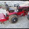
1 pointGot the dust off my son's 58RJ. He has been asking to drive it all winter but it has been in storage. Carb needed to be removed, cleaned and put back on due to jellied gas. Thought I ran it out. Enjoy my 4 year old on HIS ride..









.JPG.9f2ecb26065c66527b0730084ab7fc7a.thumb.jpg.7dc8a04d9a53d44ee2b23f26ee94496f.jpg)