
Leaderboard


Popular Content
Showing content with the highest reputation on 03/18/2012 in all areas
-
1 pointsince i posted pics of my 1057 with a solenoid for the starter generator, ive had a few inquiries about wiring diagrams and such to do this. well my 1277 without a solenoid became a candidate today because of many wiring issues and a burnt out switch. so i thought i would post a rundown on the install. the 1277 hasnt got much love since i got it xmas time, it gets moved around and thats about it. it had a few issues with wiring when i got it, but just havent had a chance to fix them and spend some time making it safe. well yesterday i went to move it and it was putting up a fight, wouldnt turn over very fast and started smoking from behind the dash. so i got the battery disconnected and left it alone until this morning. first of all i got the old wiring and switch out of there and got a few parts together to start on this. heres a few pics of what it looked like. cut wiring, bad connections and a bad switch. i already had disconnected the switch wiring before the pics.... better switch will be used to replace the burnt smoky one...... picked up some battery lug and ring crimp terminals for the 14 ga. wiring that i was going to replace. heres the solenoid i used. regular ford unit, around $7 from the local farm and fleet... first thing is to prepare the solenoid and work out where to mount it. i chose the same spot as my 1057, in behind the lift handle on the inside of the hood stand. one of the quadrant bolts is removed and replaced with a longer bolt so the solenoid can mount to it and a nut and star washer is used to fix the solenoid.. i needed to open up one of the holes on the solenoid bracket for the bolt to pass through, one fixing seems to hold it well enough. theres no moving around once the nut is tightened..... i didnt get a pic of the solenoid mounted up on the 1277, but heres the one from the 1057. same thing just ones a little cleaner.... then i moved on to making the battery cables. the battery in this is not the original style, that was a round post. im using this smaller different L/G post style battery and so the cables will be made to suit. i made the cables long enough so i could install either a left or right + handed battery. this tractor will be used with whatever battery is spare for a while, so i wanted to be able to use both orientations. now for this we need some 6 ga. cable and some wiring lugs. i used the crimp style with crimping pliers in a vise. ive made quite a few cables this way and it seems to hold the cable nice in the lugs. i worked on the bat+ to solenoid cable first. on a length of cable i put a lug on one end for the solenoid terminal post. i used the 'top' post for the battery feed and 'bottom' for the feed to the starter. you could do it either way as the solenoid doesnt care which one has the battery voltage. then measure the length for the cable and crimp the lug for that end. then i moved on to the cable that goes from the other solenoid post to the starter terminal.. and then made the neg side from the battery to the engine ground. heres the three cables done. used heatshrink on the terminals to protect the connection from the weather. now we move onto the 14 ga. wiring for the starter signal to the solenoid. since i was replacing the wiring that was bad, i also cut wire for the regulator bat circuit and cig lighter as well. these 4 wires were rough cut to 16 inches long. so we have 2 @ 14ga. red (for starter signal from solenoid BAT cable terminal to switch BAT+, and switch START terminal to solenoid S terminal.) 1@14ga. green (for ignition BAT+ to regulator BAT+) 1@14ga. black (for power from regulator L terminal to cig lighter) pic only shows 3 wires, just imagine theres a black one as well.... now use ring crimp terminals to terminate the wiring at the solenoid. crimping wire terminals...... first remove the outer cover..... then crimp using suitable pliers, i really like this style as it curls the tabs into the wire, rather than squashing them..... then when you are done make sure to heat shrink the ends...... both the red wires run to the solenoid. one wire will have a larger ring terminal to suit the larger bat post. the other will use a terminal to suit the S terminal on the solenoid. the wire that has the smaller terminal ( for the S terminal) mark the other end of it with a sharpie so we know this is for the S terminal. fix these two wires to the solenoid. now terminate one end of the green wire and one end of the black wire and fix to the regulator.... black to the L terminal, green to the BAT+ terminal. snake all 4 wires up through the grommet in the lower part of the dash and route over towards ignition switch area... the upper wire with the ring terminal is the wire to the coil + this was already in position. if you need to make a coil wire as well make sure to add this in so all wiring can be terminated and routed together neatly. i ended up cutting this terminal off and redoing it as the length wasnt right. cut a small piece of heatshrink tubing and place over all the wiring. once you have all the wires going to the switch neat and allowed enough room for the black lighter wire shrink the tubing to keep it in place so the lengths can be determined at the switch without individual wires moving. sometimes i will use zip ties for the same purpose. identify the red wire without the sharpie mark and the green and work out the length to cut to terminate at the BAT+ terminal of the switch. i used a 12ga. terminal for these two wires and crimped them together. now terminate the red wire with the sharpie mark to the START terminal and the coil + wire to the IGN terminal. also work out the correct length for the lighter wire and terminate. all these crimp terminals get heat shrink tubing over them. now i remove the wiring and making sure not to pull at it slowly snake it out from the dash and grommet and heat shrink the wiring into groups. the red wires going to the solenoid together, the green and black going to the regulator together and finally place larger heatshrink over the wires to the switch so that the lower end of the tubing covers the ends of the first two groupings of wire. make sure to do any crimp terminals with the tubing as well. now snake it all back into position and fix it all in place at the correct terminals.... at the regulator...... black to the L terminal, green to the BAT+ terminal. at the solenoid red with the large ring to the bat terminal that also has the cable from the battery + attached. red with the small ring to the S terminal on the solenoid. red and green terminated together to the BAT terminal of the switch. red from the coil+ to the IGN terminal ( this also takes one wire from the gen warning light) red with the sharpie mark to the START terminal (this takes the other wire from the gen warning light) black to the cig lighter. finish connecting the battery cables... one from the bat + to the large solenoid bat post (same terminal as one of the red wires) one from the other large solenoid bat post to the starter terminal. one from the battery - to ground on engine and/or other suitable place. just want to mention that two different batteries were used through this process. they had different post orientations. the first one has the + closest to the belt guard, the second has the + closer to the opposite side. hope this is easy enough to understand, not a real difficult job to do, just make sure your connections are good and you pay attention to where wires are meant to go. i used the colors off a factory wiring diagram, and used red for the solenoid signal which obviously wasnt on the factory non solenoid wiring.
-
1 pointI was in the process today of getting out my 2 8 speeds to get them running for the season, the kids have been asking to ride them. I pushed the 73 10 horse out, checked the oil and hit the key... A mouse came shooting out of the side of it all mangled up and doing a leg kick in the yard. Upon further review I realised I had made mouse soup! It's hard to tell but after sorting through the carnage I believe there were 2 more in there. :ychain:
-
1 pointThis is my first post, so bear with me on this one. Quick history-1998 44" 2 Stage snowthrower, Model #79361, I bought this unit off eBay for a fair price back in January 2010, from Joe's Outdoor Power. I did the rebuild during the summer of 2010. The paint color was automotive Dodge Viper red, all decals are new and I carefully removed and reattached the model/serial# tag with an automotive emblem adhesive. It was mounted on my 1991 416H for the end of 2010 winter and for the 2010-2011 season. This last winter it was on my 1995 520H. I'm not an engineer, I just tinker with stuff that breaks or doesn't work as well as I would like it to. Before and after pictures First the Peerless gearbox, I don't know if the previous owner hit something solid with the auger or the pulley was hit from the side, but where it is mounted was bent counterclockwise. I bent back the mounting surface with small hydraulic press and welded two pieces of cold rolled steel, 1/2 x 1 x 3", on the inside and remounted the gearbox with 1/2" longer carriage bolts (Sorry no picture, difficult to see). I tried a new stock chain tensioner block the first winter after the rebuild (2010-2011) and didn't like how it wore so fast. So for this winter I used a small roller chain guide with a sealed ball bearing (made for a small motorcycle), and it worked pretty well. But we had a very light winter this year. My auger bearings were worn completely through the side, I didn't like the shaft turning inside the bronze bushing so I replaced them with 1" self centering sealed ball bearings from TSC, Part #1195167 and mounting flanges, Part #1198717. Then I had to make a 1/4" spacer so the bearings sat inside far enough so the side thrust bolts on the outside ends of the shaft were spaced correctly. Next are the modifications. I added a 12 volt linear actuator to the deflector. The mounts are homemade from aluminum and I had to drill one 1/4" hole in the deflector handle. The actuator has built in stroke adjustment and limit switches. I added a 12 volt power window motor from my truck to turn the chute. This took some time to fabricate and to figure how to wire it with limit switches. The limit switches are from McMaster-Carr and are rated to get wet but not submersed. I used a standard flat four trailer plug to connect it to the tractor. The first picture is the mock up and I drilled two 3/8" hole to mount. The toggle switches I used were from Radio Shack (3 position, 6 terminal, DPDT switch, springs back to center). I also attached a power window motor to a single stage(1989-Model#06-36SL01). I bought it brand new in the box in 2009. I know this model was built for a vertical shaft Wheel Horse, but I converted it to my horizontal shaft tractors. That would be complete new post. Too much time on my hands during the winter I guess. Currently I'm putting a Haban sickle bar mower on the 416H. Not a bad fit until I wanted to use the hydraulic lift to raise and lower it. I hope this has some helpful information for somebody, as I have picked up a lot information from this site for my hobby. Craig
-
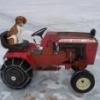
1 pointWell my great niece Jo'Leigh Nicole (Little Jo Jo) has horse fever No doubt she is cutting her Teeth on a Wheel Horse!!
-
1 pointAdded a pair of Carlisle 23x9.50x12's today to replace some leaky cheap ones.
-
1 pointwell - the name pretty much says it. I love to shoot! I too have been out of the game for a while. Spent two years in DC and obviously couldn't bring certain hobbies with me. I'm looking forward to getting back into it now that I'm back. I used to be an instructor for the Boy Scouts and my kids can all really put 'em in the bullseye down range.
-
1 pointGary would you buy me a pair for my birthday.. Good looking tires.
-
1 pointmatt heres a quote from one of my posts earlier today on jeff (hodge71) d series resto thread........... same goes here.... well my stuff definitely looks better in the pics than in person, ive got a magic camera, just sayin.................
-
1 pointDuke, Ignore AMC. The snowchucker is prettier and more productive than any of my children, and they all get their own beds!
-
1 pointhere pics of how it works
-
1 pointDeath is nothing at all I have only slipped away into the next room I am I and you are you Whatever we were to each other That we are still Call me by my old familiar name Speak to me in the easy way you always used Put no difference into your tone Wear no forced air of solemnity or sorrow Laugh as we always laughed At the little jokes we always enjoyed together Play, smile, think of me, pray for me Let my name be ever the household word that it always was Let it be spoken without effort Without the ghost of a shadow in it Life means all that it ever meant It is the same as it ever was There is absolute unbroken continuity What is death but a negligible accident? Why should I be out of mind Because I am out of sight? I am waiting for you for an interval Somewhere very near Just around the corner All is well. Nothing is past; nothing is lost One brief moment and all will be as it was before How we shall laugh at the trouble of parting when we meet again! Henry Scott Holland
-
1 pointI am loving the stickers in the last picture! The tractor turned out really nice Stephen! Glad you were able to get it done. You have been busy for sure!
-
1 pointHere's the hitch on my 704.
-
1 pointYes the rears are 12" if they fit a 1961 tractor they will probably fit just about any tractor with 8" fronts and 12" rears, we would have to see the weights to give you more info.

This leaderboard is set to New York/GMT-05:00